| ISO attribute | Explanation |
| ADIF1 | Additional information 1 |
| ADIF2 | Additional information 2 |
| ADIF3 | Additional information 3 |
| ADJLN | Minimum adjustment limit |
| ADJLX | Maximum adjustment limit |
| ADJRG | Adjustment range |
| AN | clearance angle major |
| AP1 | depth of cut split |
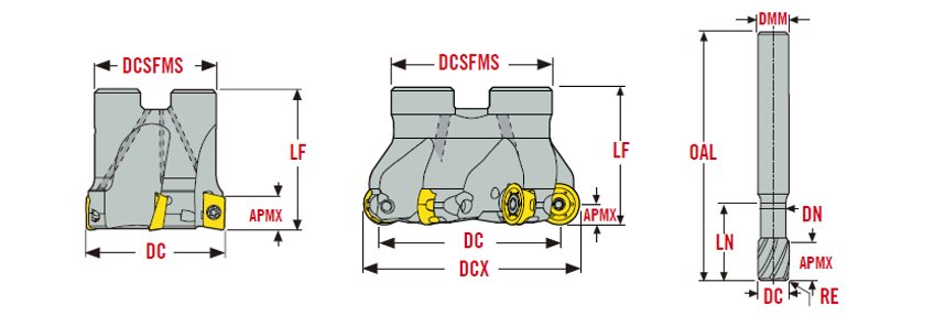
| APMX | Depth of cut maximum |
| APMXE | Depth of cut maximum in feed direction end |
| APMXS | Depth of cut maximum in feed direction side |
| AZ | Plunge depth maximum |
| AZ | Maximum plunge depth |
| B | shank width |
| BAWS | workpiece side body angle |
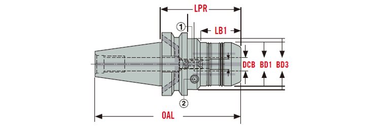
| BD | Body diameter |
| BD1 | Body diameter 1 |
| BD2 | Body diameter 2 |
| BD3 | Body diameter 3 |
| BDX | Body diameter maximum |
| BEC | Back end chamfer angle |
| BHTA | Body half taper angle |
| BHTA1 | Body half taper angle 1 |
| BLQ | balance quality code |
| BN | Face land width |
| BS | Wiper edge length |
| C | Keyway depth |
| CA | collision angle |
| CBDP | Connection bore depth |
| CBTHN | Connection body thickness |
| CCER | Curved cutting edge radius |
| CDRX | cutting depth radial maximum |
| CDX | Cutting depth maximum |
| CDXI | cutting depth maximum insert |
| CDXSH | cutting depth maximum shank |
| CEDC | Cutting edge count |
| CF | Spot chamfer |
| CHA | Cross hole angle |
| CHW | Corner chamfer width |
| Cmax | Helical interpolation hole diameter maximum |
| Cmin | Helical interpolation hole diameter minimum |
| CND | Coolant entry diameter |
| CNDP | Coolant entry depth |
| CNT | coolant entry thread size |
| CP | max coolant pressure |
| CP | coolant pressure |
| CPNDIA | Connection pin diameter |
| CRKS | Connection retention knob thread size |
| CTMS | Connection text machine side |
| CTWS | connection text workpiece side |
| CUTDIA | work piece parting diameter maximum |
| CW | Cutting width |
| CZC | Connection size code |
| D1 | fixing hole diameter |
| DC | Cutting diameter |
| DC1 | Cutting diameter 1 |
| DCB | Connection bore diameter |
| DCB1 | Connection bore diameter 1 |
| DCB2 | connection bore diameter 2 |
| DCBN | Connection bore diameter minimum |
| DCBX | Connection bore diameter maximum |
| DCC | Design configuration style code |
| DCINN | cutting diameter internal minimum |
| DCINN | Minimum cutting diameter internal |
| DCINN2 | cutting diameter internal minimum 2 |
| DCINN3 | cutting diameter internal minimum 3 |
| DCINX | Maximum cutting diameter internal |
| DCN | Minimum cutting diameter |
| DCN | Cutting diameter minimum |
| DCON | Connection diameter |
| DCP | data chip provision |
| DCSFMS | Contact surface diameter machine side |
| DCSFWS | Contact surface diameter work piece side |
| DCX | Cutting diameter maximum |
| DCX | Maximum cutting diameter |
| DF | flange diameter |
| DIX | tool changer interference diameter maximum |
| DMM | Shank diameter |
| DN | Neck diameter |
| DUO | DUO Jetstream Tooling Duo, see page 85, 89, 98 |
| EPSR | insert included angle |
| FCEDC | face cutting edge count |
| FDESU | Feed direction suitability end |
| FDP | Feed direction primary |
| FDSSU | Feed direction suitability side |
| FHA | Flute helix angle |
| FLGT | Flange thickness |
| FLGW | Flange width |
| GAMF | Rake angle radial |
| GAMO | Rake angle orthogonal |
| GAMP | Rake angle axial |
| GAN | Insert rake angle |
| GB | Face land angle |
| H | shank height |
| HC | Thread height actual |
| HF | functional height |
| HRY | measure, Measure from ref. plane of mounting to bottom plane of unit in direction Y m |
| HTB | Body height |
| IC | Inscribed circle diameter |
| ICC | internal coolant channel |
| INPLM | minimum initial plunge diameter |
| INPLX | initial plunge maximum |
| INSD | Insert diameter |
| INSL | Insert length |
| KAPRE | Tool cutting edge angle in feed direction end |
| KAPRS | Tool cutting edge angle in feed direction side |
| KCH | Corner chamfer angle |
| KCHL | corner chamfer angle left hand |
| KCHR | corner chamfer angle right hand |
| KRINS | Major cutting edge angle |
| KWW | Keyway width |
| L | Cutting edge length |
| L2 | cutting edge length 2 |
| LAMS | inclination angle |
| LB | Body length |
| LB1 | body length 1 |
| LB2 | body length 2 |
| LB3 | Body length 3 |
| LB4 | Body length 4 |
| LCF | Chip flute length |
| LCOG | length to center of gravity |
| LCOG | Position of the center of gravity |
| LE | Cutting edge effective length |
| LF | Functional length |
| LF2 | functional length_2 |
| LFN | Minimum functional length |
| LFS | functional length secondary |
| LFS | Secondary functional length |
| LH | head length |
| LH2 | head length 2 |
| LIG | insert gauge length |
| LN | neck length |
| LN2 | neck length 2 |
| LPR | Protruding length |
| LS | Shank length |
| LSC | clamping length |
| LSCN | Clamping length minimum |
| LSCX | Clamping length maximum |
| LU | usable length |
| LUX | Usable length maximum |
| LUX | Maximum usable length |
| M | M-dimension |
| NA | neck angle |
| OAH | overall height |
| OAL | Overall length |
| OAW | overall width |
| PCEDC | peripheral cutting edge count |
| PDX | Profile distance ex |
| PL | Point length |
| PNA | Profile included angle |
| PRFA/2 | profile angle divided by two |
| PRFRAD1 | profile radius 1 |
| PRFRAD2 | profile radius 2 |
| PRFRAD3 | profile radius 3 |
| PSIR | tool lead angle |
| PSIRL | cutting edge angle major left hand |
| PSIRR | cutting edge angle major right hand |
| RA | Relief angle |
| RADH | radial body height |
| RADW | radial body width |
| RE | Corner radius |
| RE2 | corner radius 2 |
| RETL | flank radius left hand |
| RETR | flank radius right hand |
| RFID | Data chip provision |
| RL | Radial location (of the balancing screw) |
| RMPX | Ramping angle maximum |
| RoundedUpWeight | roundedUpWeight |
| RP | Programming radius |
| RPM | Rotational speed |
| RPMX | Rotational speed maximum |
| S | Insert thickness |
| S1 | Insert thickness alt 1 |
| SA | sphere angle |
| SIG | Point angle |
| SRR | Recommended stock removal |
| SW | Wrench size |
| TACH | Cutting half taper angle |
| TDZ | Thread diameter size |
| TDZ1 | Thread diameter size 1 |
| TDZ2 | Thread diameter size 2 |
| THUB | Hub thickness |
| TPI | threads per inch |
| TTL | TRUE tip length |
| UTCN | Uncut thickness |
| W1 | Insert width |
| WB | Body width |
| WDX0 | maximum working depth 0 degree |
| WDX05 | maximum working depth 0.5 degree |
| WDX1 | maximum working depth 1 degree |
| WDX15 | maximum working depth 1.5 degree |
| WDX2 | maximum working depth 2 degree |
| WDX3 | maximum working depth 3 degree |
| WF | functional width |
| WF2 | functional width 2 |
| WFS | functional width secondary |
| ZEFP | Peripheral effective cutting edge count |
| ZNP | Peripheral mounted insert count |