Mitä on värinä koneistuksessa ja kuinka sitä vähennetään?
Kun aaltoliikettä tapahtuu tasapainopisteen ympärillä, ne tuottavat mekaanisen ilmiön, joka tunnetaan nimellä värähtely. Koneistuksessa värinä – tyypillisesti lastuamisvoimien tai työstökoneen itsensä aiheuttama – johtaa ei-toivottuun tulokseen. Merkittävän kilpailuedun saavuttamiseksi sinun on ymmärrettävä värinän syyt ja osattava voittaa ne.Värinä on mekaaninen ilmiö, joka tapahtuu tasapainopisteen ympärillä. Nämä heilahtelut voivat olla jaksollisia, kuten heilurin heilahteluja, tai satunnaisia, kuten renkaan liike sorateillä.
Joskus värinä on toivottavaa. Esimerkiksi matkapuhelin toimii oikein, koska ääni on ilman värähtelyä. Useimmiten värinä kuitenkin hukkaa energiaa samalla kun se aiheuttaa ei-toivottuja muodonmuutoksia ja melua. Esimerkiksi suurin osa käytössä olevien moottoreiden, sähkömoottoreiden ja muiden mekaanisten laitteiden värinästä on ei-toivottua. Epätasapainoiset pyörivät osat, epätasainen kitka, hammaspyörien hampaiden kosketus ja muut toiminnot voivat aiheuttaa värinää, joka huolellisella suunnittelulla yleensä minimoidaan.
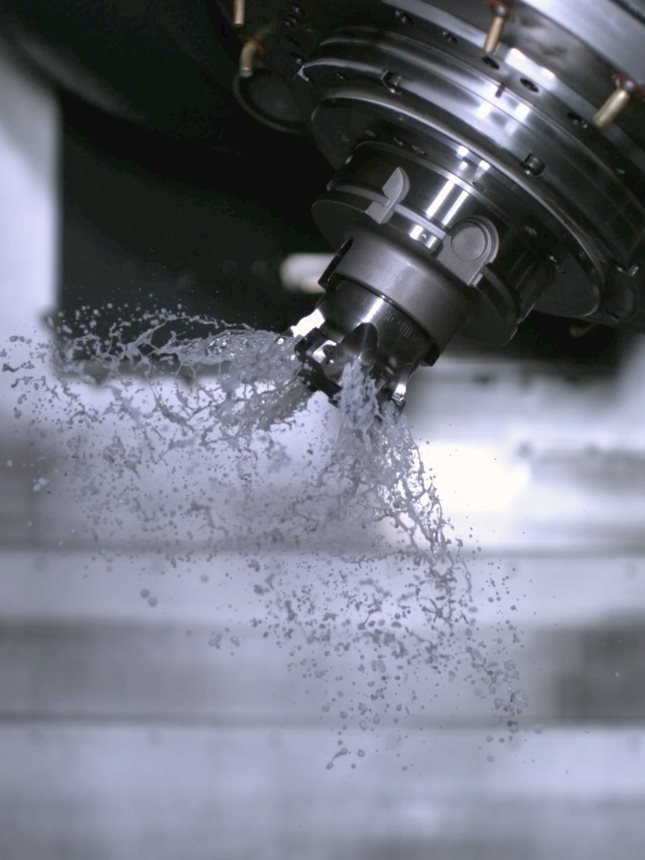
Kuva 1 Värinä koneistuksessa
Työstökoneet, työkappaleet ja työkalut eivät ole täysin jäykkiä, ja lastuamisvoimat voivat saada ne värisemään. Koneen, työkappaleen ja pitimen dynaamiset ominaisuudet voivat rajoittaa lastuamistehoa. Liian pieni jäykkyys sekä riittämätön värinänvaimennus voivat johtaa ongelmiin itseherättyneen värinän tai "epätasaisen pinnan" kanssa. Ilmiön perustiedolla epätasaisuudesta tulee ennustettavaa, mikä mahdollistaa paremman lastuamistapahtuman.
värinä koneistuksen aikana aiheuttaa monia kielteisiä seurauksia, joista tärkeimpiä ovat seuraavat:
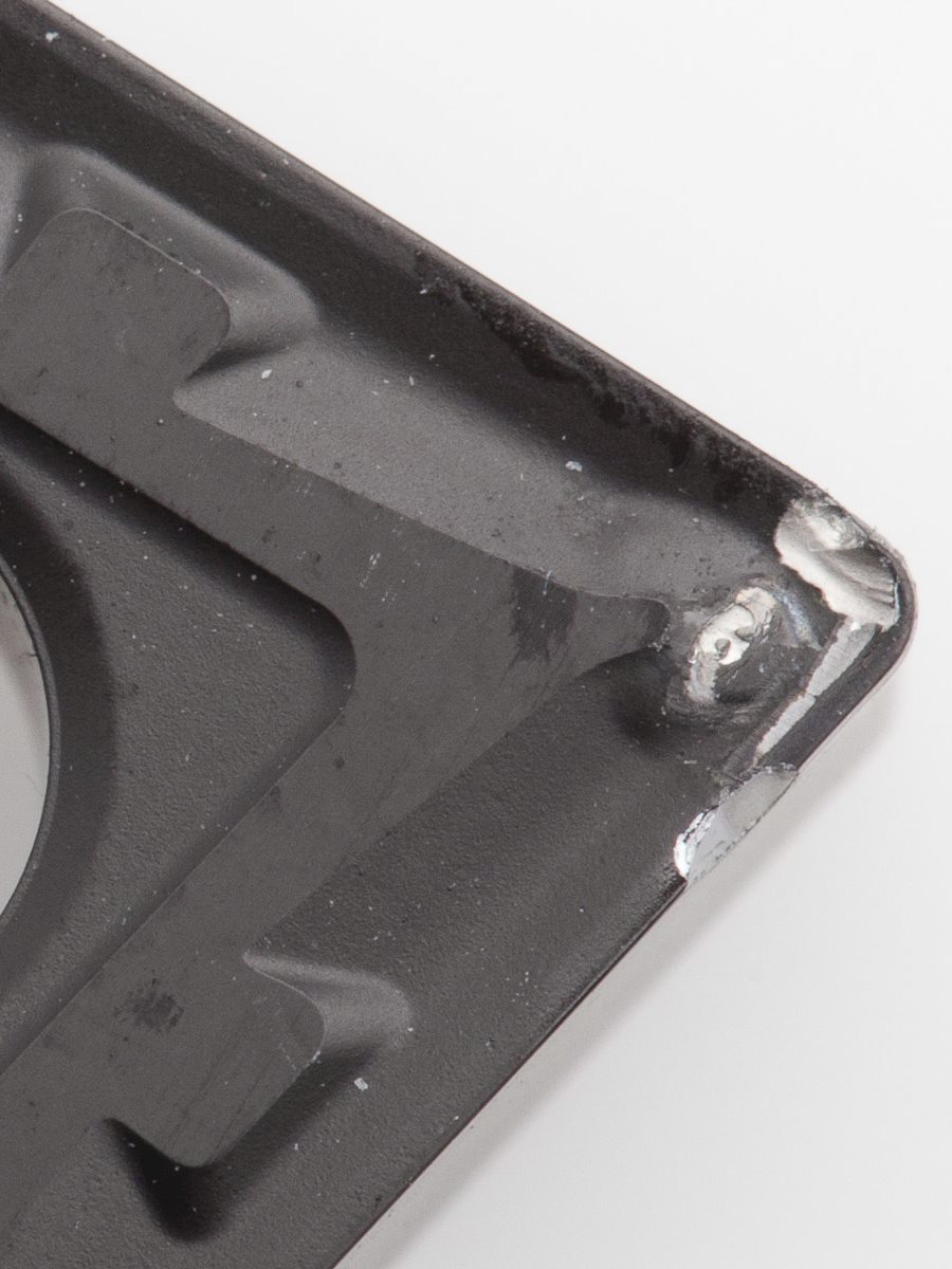
- Lastuamissärmien ylimääräinen kuluminen ja hallitsemattomat, arvaamattomat kulumiskuviot (esim. halkeilevat ja halkeilevat reunat), jotka heikentävät koneistuksen luotettavuutta.
- Huonottunut pinnanlaatu, susikappaleet tai työkappaleen lisäkoneistus. Näin ollen värinä vaikeuttaa koneistusta ja voi johtaa ongelmiin toimitusajoissa ja toimitusvarmuudessa.
- Kahdella edellisellä värinän vaikutuksella on myös negatiivinen vaikutus talouteen. Värinä maksaa rahaa.
- Koska värinä vaatii energiaa, se myös kuluttaa energiaa sekä haastaa koneistajien ammattitaidon.
Ota yhteyttä jos värinä haasteena
Tutustu tähän artikkeliin liittyvään sisältöön löytääksesi ratkaisumme
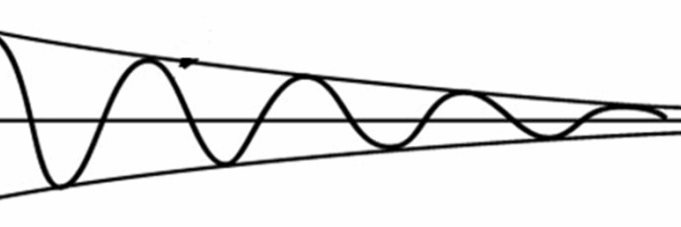
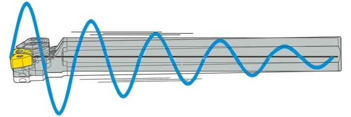
Kuva 2 Vapaa värinä
Vapaa värinä syntyy, kun ulkoinen tekijä laukaisee värähtelyn mekaanisessa järjestelmässä, joka sitten värähtelee vapaasti. Tämä on verrattavissa siihen, mitä tapahtuu, kun vedät lapsen keinua taaksepäin ja vapautat sen. Mekaaninen järjestelmä värähtelee sitten yhdellä tai useammalla "luonnollisella taajuudellaan" ja vaimenee nollaan.
Pakkovärähtelyä syntyy, kun mekaaniseen järjestelmään kohdistuu ajallisesti muuttuva häiriö (kuormitus, siirtymä tai nopeus). Häiriö voi olla jaksollinen, vakaan tilan tulo tai satunnainen tulo. Kun epätasapainoinen pesukone värisee tai rakennus tärisee maanjäristyksen aikana, nämä ovat esimerkkejä pakotetusta värinästä.
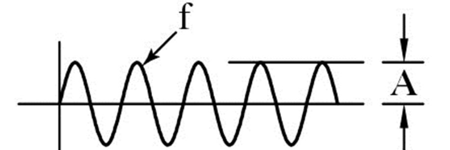
Kuva 3 Pakotetut värinät (f = frekvenssi ja A = Amplitudi)
Järjestelmän taajuusvaste on yksi pakotetun värähtelyn tärkeimmistä ominaisuuksista. Ilmiössä, jota kutsutaan resonanssiksi, värähtelyn amplitudi voi nousta erittäin suureksi, kun pakotustaajuus lähestyy kevyesti vaimennetun järjestelmän luonnollista taajuutta. Järjestelmän ominaistaajuutta kutsutaan resonanssitaajuudeksi. Kun työnnät lasta keinussa, sinun on työnnettävä oikealla hetkellä, jotta keinu nousee korkeammalle ja korkeammalle, eikä suuri liike vaadi suurta voimaa. Työntöjen tarvitsee vain lisätä energiaa järjestelmään. Roottorin laakerijärjestelmissä mitä tahansa pyörimisnopeutta, joka herättää resonanssitaajuuden, kutsutaan kriittiseksi nopeudeksi.
Resonanssi mekaanisessa järjestelmässä voi johtaa järjestelmävikaan. Tästä syystä tärinäanalyysin on ennakoitava, milloin tämän tyyppistä resonanssia voi esiintyä, ja määritettävä ennaltaehkäisevät toimenpiteet. Lisävaimennus voi vähentää värinän voimakkuutta merkittävästi, samoin kuin järjestelmän jäykkyyden tai massan muuttaminen siirtämään luonnollista taajuutta pois pakotustaajuudesta. Jos järjestelmä ei voi muuttua, voi pakotustaajuus muuttua (esimerkiksi muuttamalla voiman tuottavan koneen nopeutta).
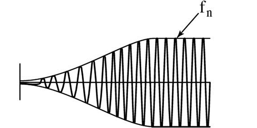
Kuva 4 Resonanssivärähtelyt
Tutustu mikrovärinät koulutukseen
The same forces that cut metal also act on the cutting tool. Nämä voimat muuttavat ja taivuttavat työkalua ja voivat aiheuttaa värinää.
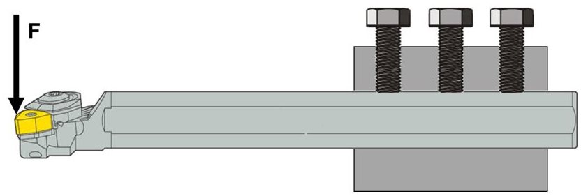
Figure 5 Cutting forces and lack of tool strength cause vibration in metal cutting.
The dynamic nature of cutting forces can lead to resonance vibration. The risk of such a situation increases with slender cutting tools or workpieces, overly high cutting forces, tool or workpiece materials that lack damping capacity, incorrect cutting methods or improper tool geometry.
Figure 6 shows a steel tool holder (diameter 100 mm and 500 mm overhang length).

Figure 6 In some situations, dynamic cutting forces can lead to resonance vibration
With a static cutting force of 500 N, this tool would deflect by 25 µm. If the cutting force varied in a sinusoidal pattern at 142 Hz, variable deflection would occur, with an amplitude 20 times greater than the static deflection. This would lead to resonance vibration.
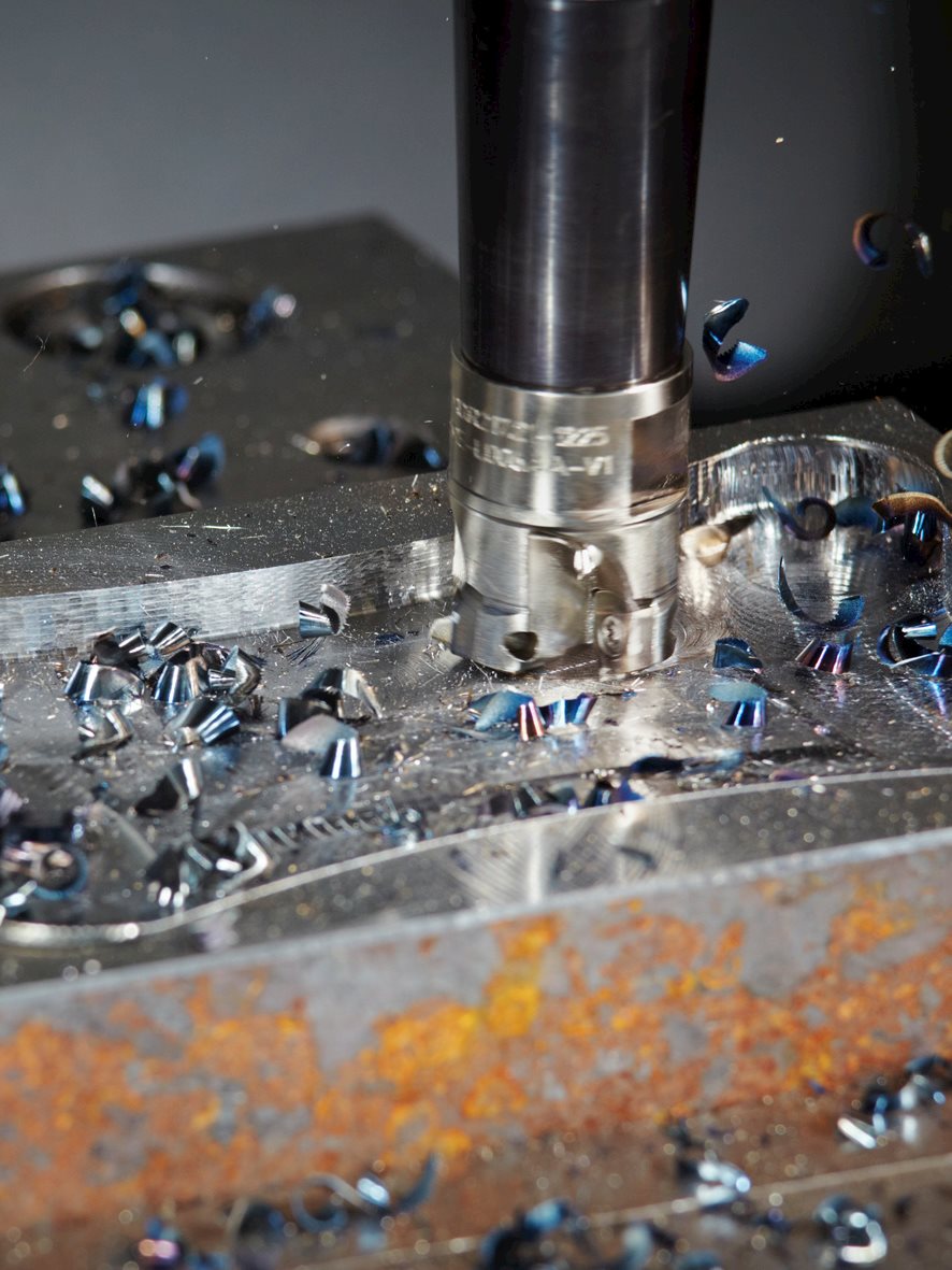
Resonance vibration can occur when the frequency with which the cutting force impacts on the cutting edge equals the Eigenfrequency (resonance frequency) of the cutting tool. Changes in cutting conditions (milling), strong, intermittent chip fragmentation or even an irregularity in the material structure could cause this situation (see Figure 7).
Machinists also refer to resonance vibration as chatter. In and of itself, chatter is not really an issue, but in some situations, chatter can endanger the quality of the process through uncontrollable cutting-edge wear or imperfectly machined workpiece surface finish. These cases require suppression of chatter, which is easiest to achieve through modified cutting conditions or, in a second stage, through modified tool selection.
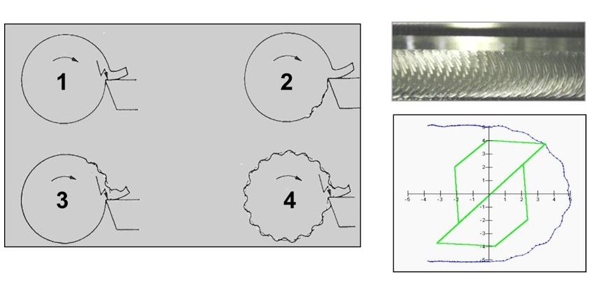
Figure 7 An irregularity in the material structure could cause vibration
In the example above, phase 1 represents a situation in which a material irregularity creates a dynamic component in the cutting force. In phase 2, this irregularity in the workpiece material causes variation in chip thickness. This leads to continuous dynamic cutting forces, and when their frequency nears the Eigenfrequency of the tool, resonance vibration can occur.
Any analysis of vibration and its risks during machining must consider the stability of the machine tool. A machine tool cannot provide limitless stability and in general, as the rotational speed of a machine-tool spindle increases, tool stability drops (see Figure 8).
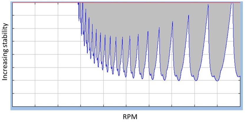
Figure 8 Stability lobes (Tlusty and Tobias) for a machine tool.
In general, the higher the rpm (revolutions per minute) at which a machine tool operates, the greater the risk of vibration. At certain speeds, however, stability increases. The selected rpm for a specific cutting tool could fall within a low-stability range, triggering vibration and the need to slow the machine to eliminate it. Conversely, the selected rpm could fall within a region of high stability, enabling cutting conditions to remain at a high level. To avoid vibration, especially during higher-rpm machining, select speeds carefully.
In general mechanics, the model shown below (Figure 9) determines the bending of a one-sided clamped cylindrical beam (e.g., an internal turning tool holder, a milling cutter, a drill, and so on). In simpler, general terms, the greater the bending or deflection, the higher the risk of detrimental vibration, including resonance vibration – and reduced tool bending or deflection reduces vibration risk.
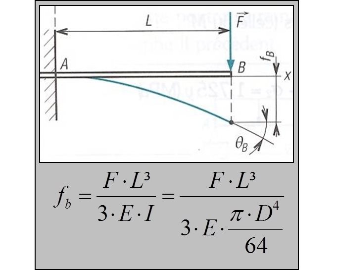
Figure 9 Relationship among bending, force and the principal dimensions of a one-sided clamped cylindrical beam.
Seen in this way, reduced vibration risk calls for minimized tool deflection or bending.
This can be achieved in several ways.
- Reduce cutting forces or change the direction in which cutting forces act on the system.
- Make the tool stronger, with a higher resistance against bending. The formula in Figure 10 shows that doubling the overhang length increases deflection by a factor of 8, whereas doubling the diameter reduces deflection by a factor 16. Therefore, shorter tools or bigger tools carry less risk of vibration. Thus, the overhang ratio (L/D = unsupported length, or overhang, divided by the diameter) often provides a measurement for quick analysis of vibration risk. Some guidance based on the overhang ratio:
- Vibration typically does not occur if the overhang ratio is less than 3.
- Vibration risk creeps in if the overhang ratio is less than 6.
- Vibration is likely to occur if the overhang ratio is less than 9.
- if the overhang ratio is greater than 9, vibration is a certainty, and classic tooling often cannot solve the problem.
- Use stiffer tool material. The modulus of elasticity (E) is a prime element. Replace a steel tool shank with carbide, for example, and deflection drops by up to 50%. This approach can be combined with the use of tapered tooling.
When you use the overhang ratio to help predict the risk of vibration, do so with careful consideration. Further analysis of the formula in Figure 9 leads to the formula shown in Figure 10, which is very revealing when written in this form and applied to two examples. First, a tool with an overhang length of 200 and a diameter of 50 mm would have an overhang ratio of 4. Second, another tool with a length of 100 mm and a diameter of 25 mm also would have an overhang ratio of 4. Would both these tools show the same risk of vibration? Apply these values for the two tools in the formula in Figure 10, and you discover that the second tool displays twice the bending and thus double the vibration risk.
When vibration risks are high, the diameter of the tool is most important.
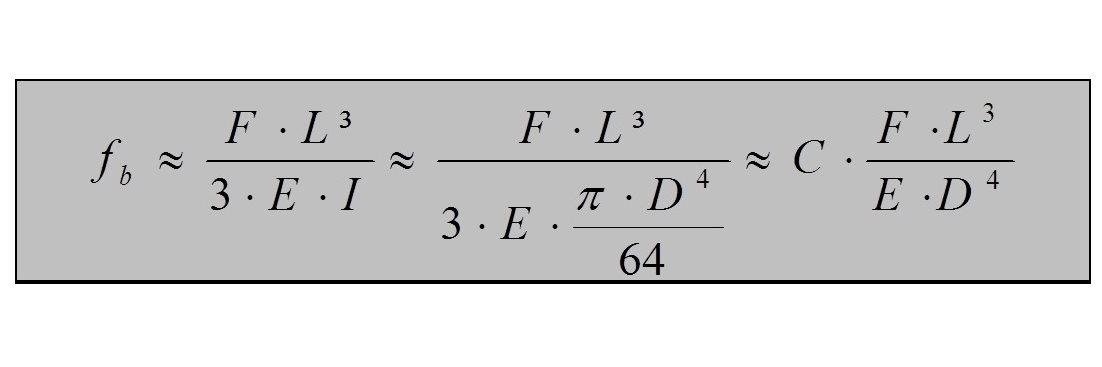
Figure 10 Bending as a function of overhang length and diameter.
Some practical steps can minimize or avoid the risk of vibration. Use all these steps to change the magnitude of or the direction in which the cutting forces act on the cutting tool.
- Use a cutting-edge angle close to 90°.
- Use a smaller nose radius and/or a sharper cutting edge.
- Reduce the cutting depth and increase the feed.
- Muuta lastuamisnopeutta.
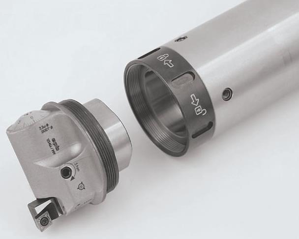
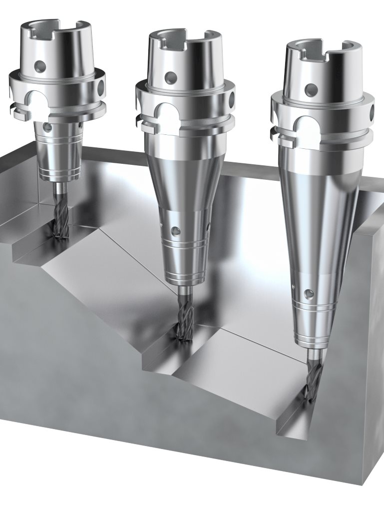
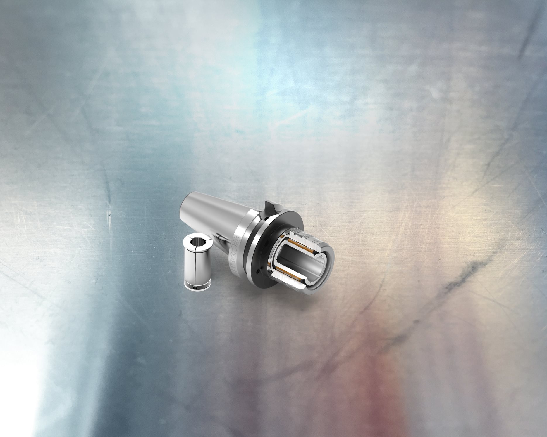
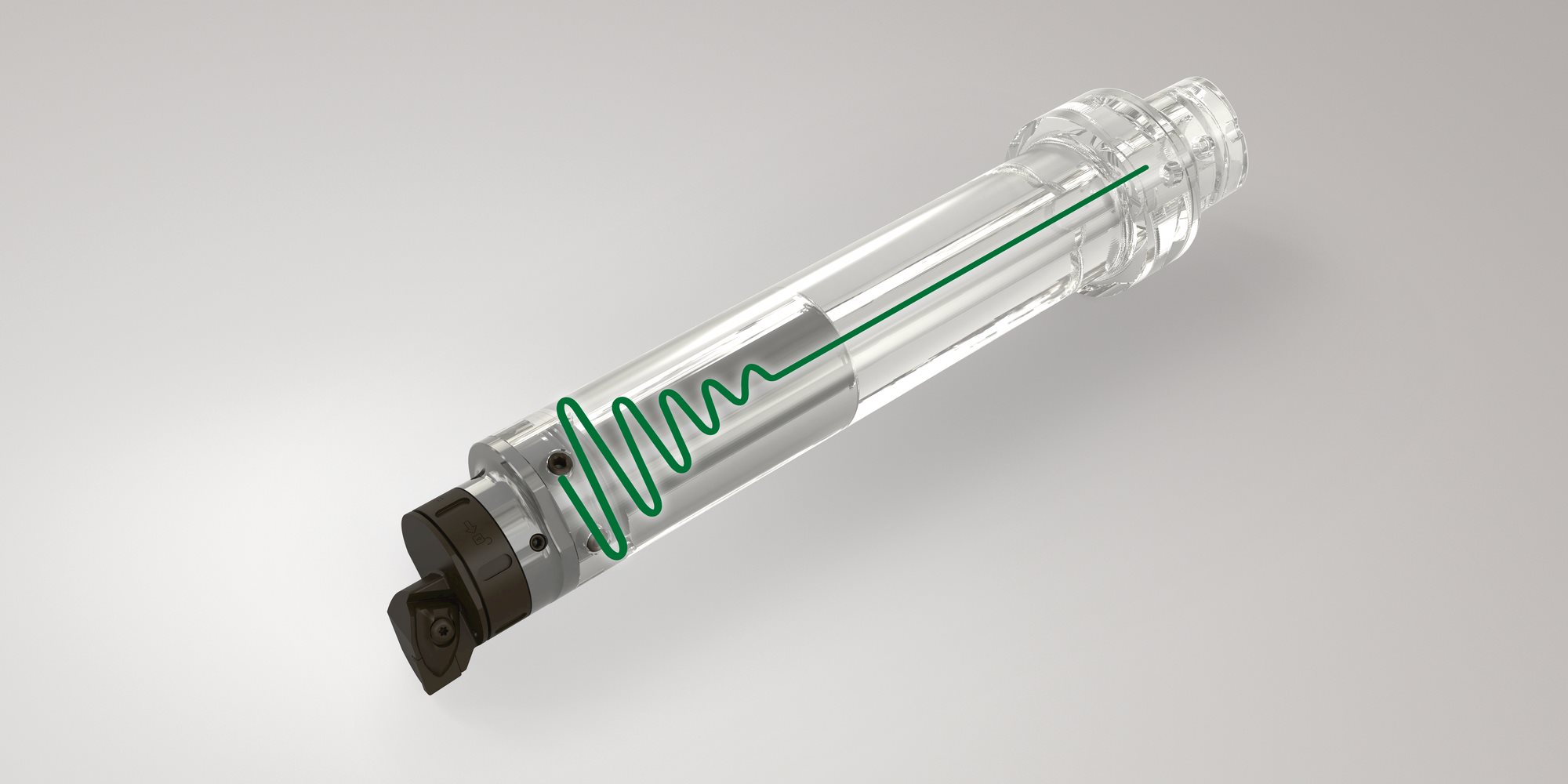
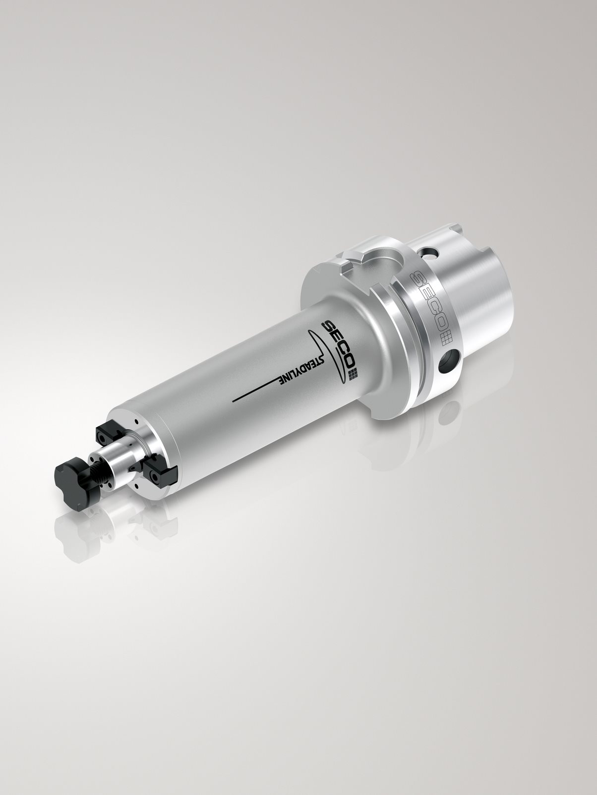
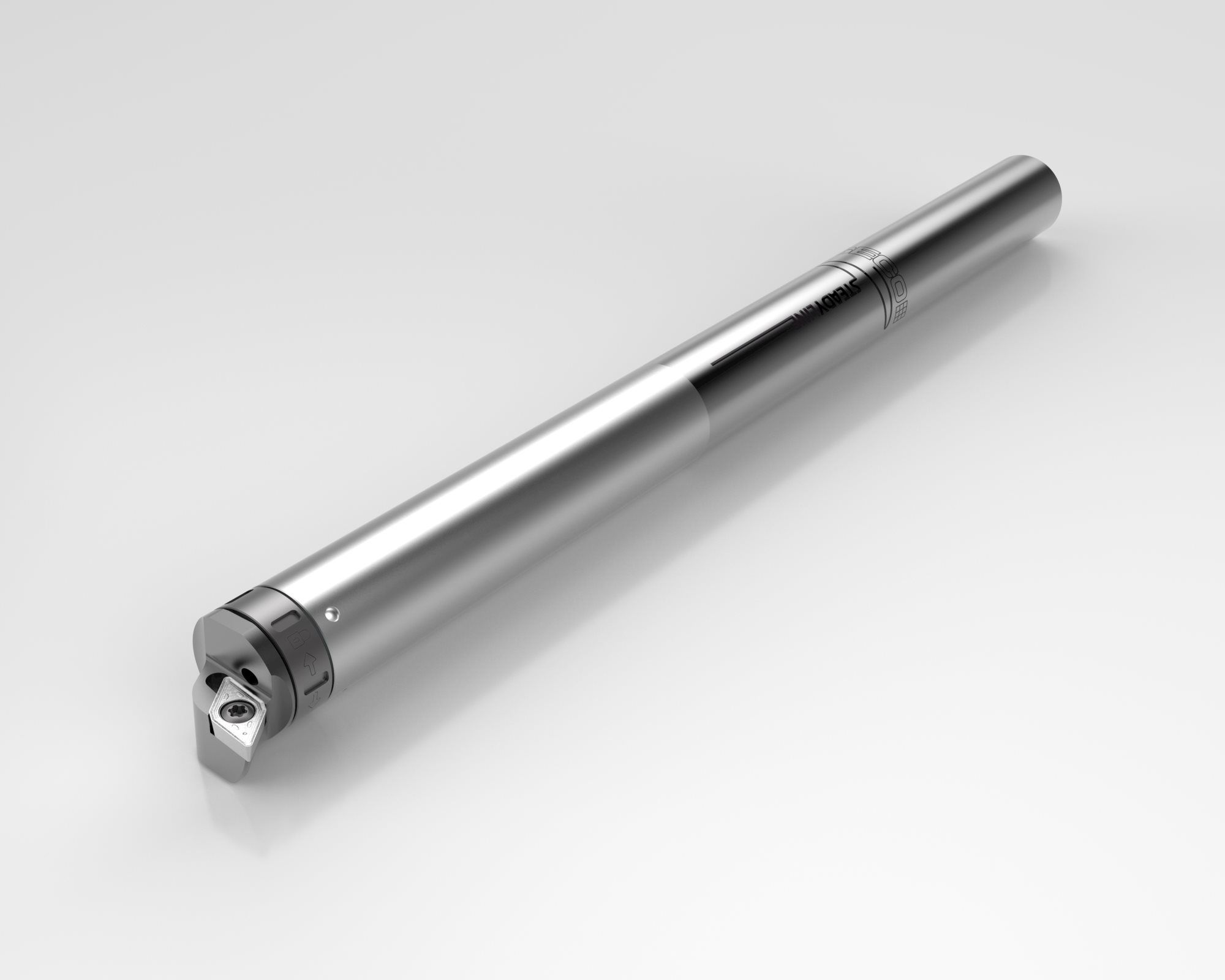
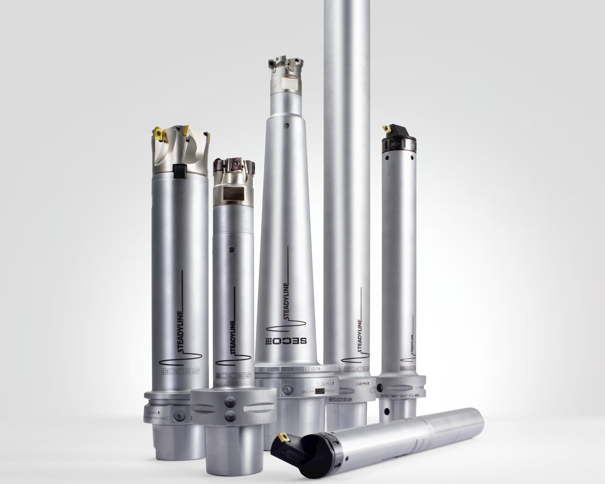
- Use a better tool clamping system (e.g., Seco-Capto and Seco Steadyline tooling).
Apply the first advice – use a cutting-edge angle close to 90° – differently in a milling application. As in turning, the resulting cutting forces will act roughly perpendicular to the cutting edges (Figure 12). As you consider the milling cutter clamped in the spindle of the milling machine and evaluate the risk of bending (Figure 13), determine the risk of vibration based on the cutting force multiplied by the distance between the direction of the cutting force and a "reference" point in the spindle. Every machine tool spindle includes a fixed reference point around which the spindle can swing.
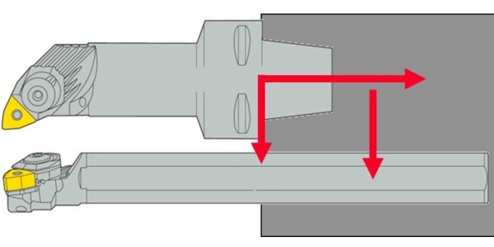
Figure 11 Better clamping of the cutting tool reduces the risk for vibrations.
When you compare a square shoulder milling cutter (cutting edge angle of 90°) with a high feed milling cutter (cutting edge angle of only a few degrees), the distance between the direction of the cutting force and the reference point is smaller, hence the risk of vibration (with the same cutting forces) is less.
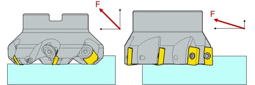
Figure 12 The size and direction of the cutting force for a milling cutter (approximately perpendicular to cutting edge).
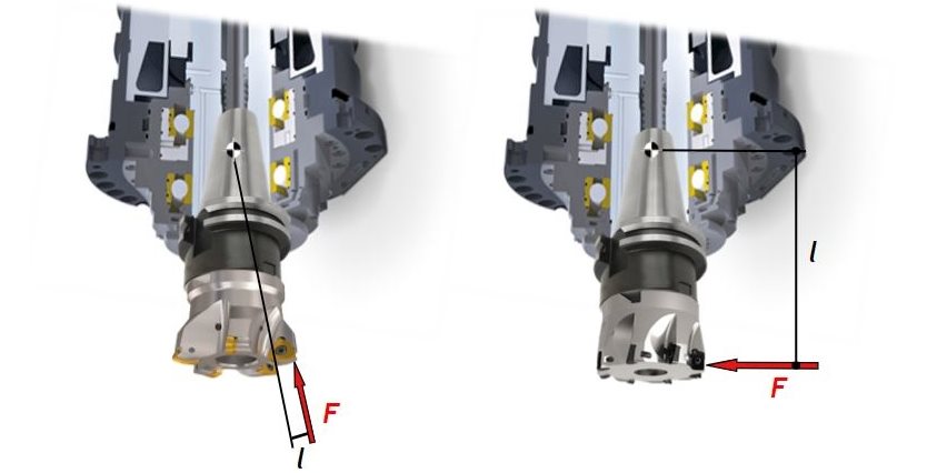
Figure 13 (F x l) determines the risk of vibration in milling.
To address vibration problems in milling, select appropriate tools and cutting conditions to change the size and direction of cutting forces.
- Choose milling cutters with a coarse pitch and clamp them with the smallest possible overhang.
- Select cutting edges with positive geometries.
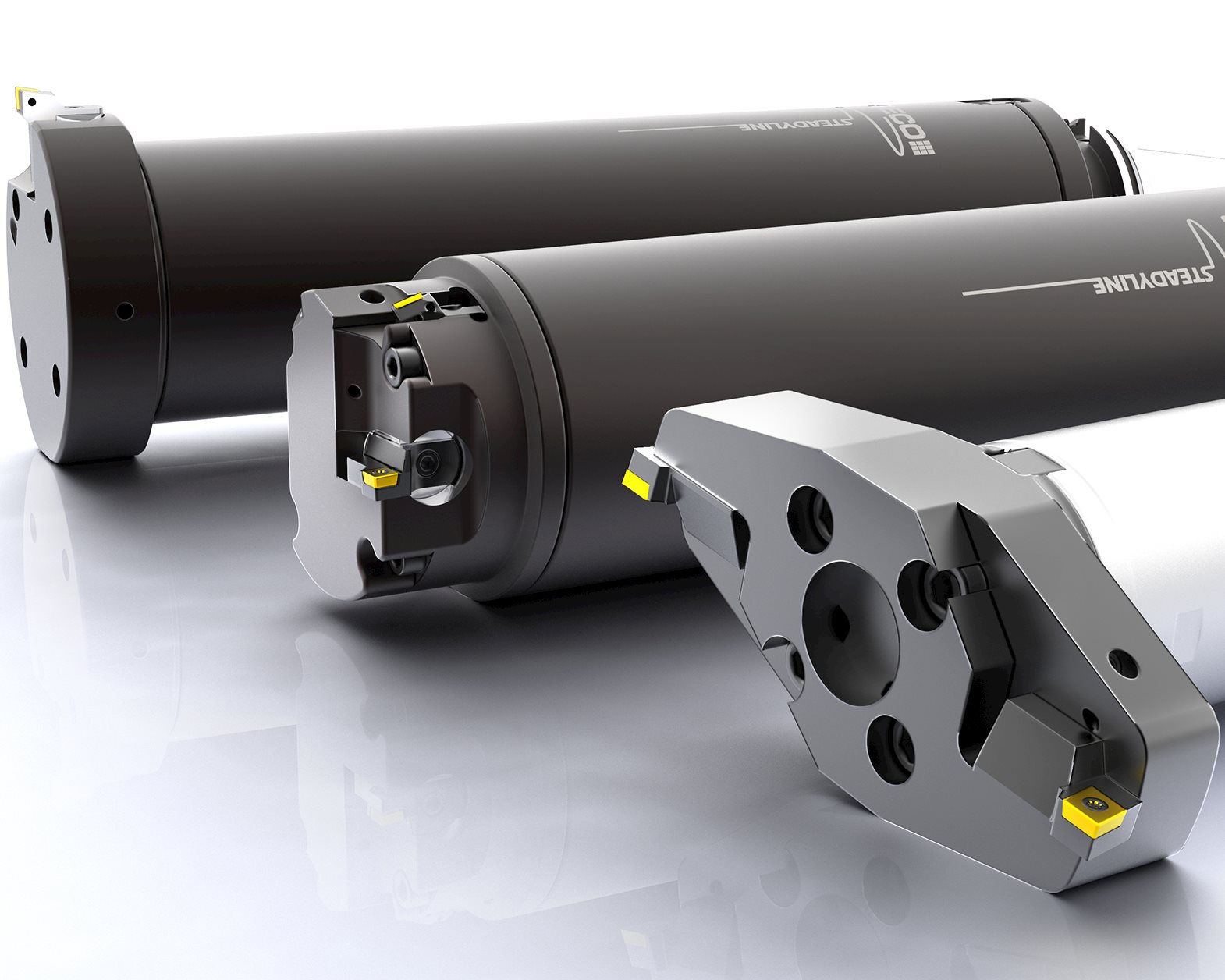
- Select a milling cutter with a smaller diameter, especially with Steadyline tooling.
- Select a small cutting-edge radius.
- Select carbide grades with a thinner coating.
- Use big feeds per tooth. Reduce the rotation speed and maintain the table feed for larger feeds per tooth. Do not reduce the feed per tooth when vibration occurs.
- Aksiaalisen ja radiaalisen lastuamissyvyyden suhde
- Use stable milling cutter clamping systems. With modular tool holding systems, use the largest possible connection size. Use tapered tool holding.
- Position the milling cutter at the center of the workpiece. Apply up-milling techniques.
Start with normal feeds and cutting speeds. If vibration arises, gradually make changes as follows:
- Lisää syöttöä.
- Lisää lastuamisnopeutta.
- Vähennä lastuamisnopeutta.
- Reduce the feed until vibration disappears or at least is minimized.
The following steps affect turning results. Use them as a checklist for vibration troubleshooting.
- Select the basic tooling system and dimensions for maximum stability and rigidity. Clamp tools with the shortest-possible overhang. This produces a higher natural frequency of the tool and reduces deflection, which makes it easier to avoid vibration or damp it if it occurs.
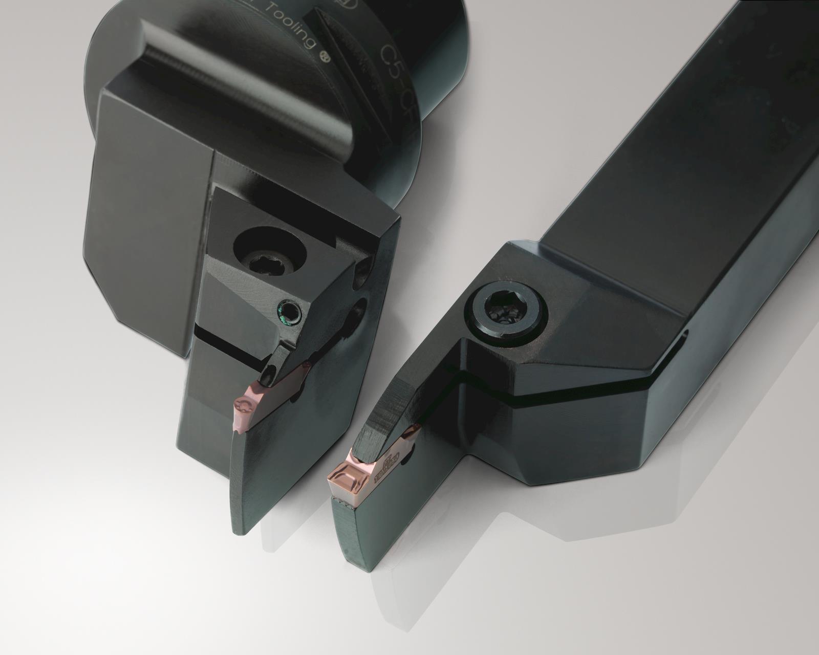
- Select the type and size of the insert and nose radius carefully. Choose the smallest-possible nose radius, and make it less than the depth of cut if possible to lower the passive cutting force. Limit depth of cut to minimize tool deflection and guarantee correct machining tolerances for the workpiece. When vibration is likely, choose an insert with a small top angle (60° or 55°) to combine light cutting with good edge strength.
- Select an insert with sharp cutting and cutting-edge geometry for easy cutting and little tool deflection. Note that sharper cutting edges are weaker and require proper chip breaking.
- Select an insert with a tougher carbide grade and sharper geometries, although this produces cutting edges with less strength that could chip or break prematurely. To increase cutting-edge reliability and tool life, compensate for weaker geometry with tougher cutting material.
- Carefully select cutting conditions to minimize depths of cut. With serious vibration risk, use a feed that is at least more than 25% of the nose radius. Evaluate the cutting speed to avoid working in an rpm zone with less machine-tool stability.
The following steps affect boring results. Use them as a checklist for vibration troubleshooting.
- Check the overhang ratio and modify the tool if necessary. Can you use a larger tool diameter? A tapered tool type? A modular tool type with a different diameter?
- Use the best-possible tool clamping (Seco-Capto).
- Place the cutting edge at center height.
- Select cutting edges with positive geometries and a small radius. Select carbide grades with a thinner coating.
- Select the type and size of the insert and nose radius carefully. Choose the smallest-possible nose radius, and make it less than the depth of cut if possible to lower the passive cutting force. Limit depth of cut to minimize tool deflection and guarantee correct machining tolerances for the workpiece. When vibration is likely, choose an insert with a small top angle (60° or 55°) to combine light cutting with good edge strength.
- Select an insert with sharp cutting and cutting-edge geometry for easy cutting and little tool deflection. Note that sharper cutting edges are weaker and require proper chip breaking.
- Select an insert with a tougher carbide grade and sharper geometries, although this produces cutting edges with less strength that could chip or break prematurely. To increase cutting-edge reliability and tool life, compensate for weaker geometry with tougher cutting material.
- Carefully select cutting conditions to minimize depths of cut. With serious vibration risk, use a feed that is at least more than 25% of the nose radius. Evaluate the cutting speed to avoid working in an rpm zone with less machine-tool stability.
Do you want to know more? We're happy to help you optimize your machining conditions and results.
Ota yhteyttä
Inline Content - Survey
Current code - 5fce8e61489f3034e74adc64