All you need to know about vibrations in solid end milling
What are some key factors that influence vibrations, how can you prevent them and how can you predict them?
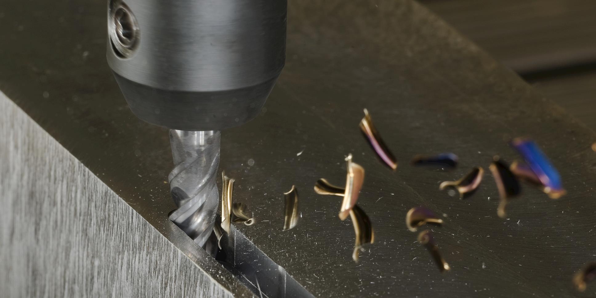
In solid end milling, vibration refers to the back-and-forth movements between the cutting tool and the workpiece during machining. While a certain level of micro-vibration is always present and often harmless, excessive vibration can escalate into chatter which negatively affects surface finish, shortens tool life and can damage the spindle or other machine components. So, managing vibration is essential for maintaining machining precision and productivity.
Chatter happens when the cutting forces change rapidly as each edge of the end mill engages and disengages with the workpiece. These changing loads can cause the tool or workpiece to shake, especially if your set-up isn’t stable enough. Once chatter begins, it can build momentum making it difficult to control without adjusting cutting parameters or improving the stability of your set-up.
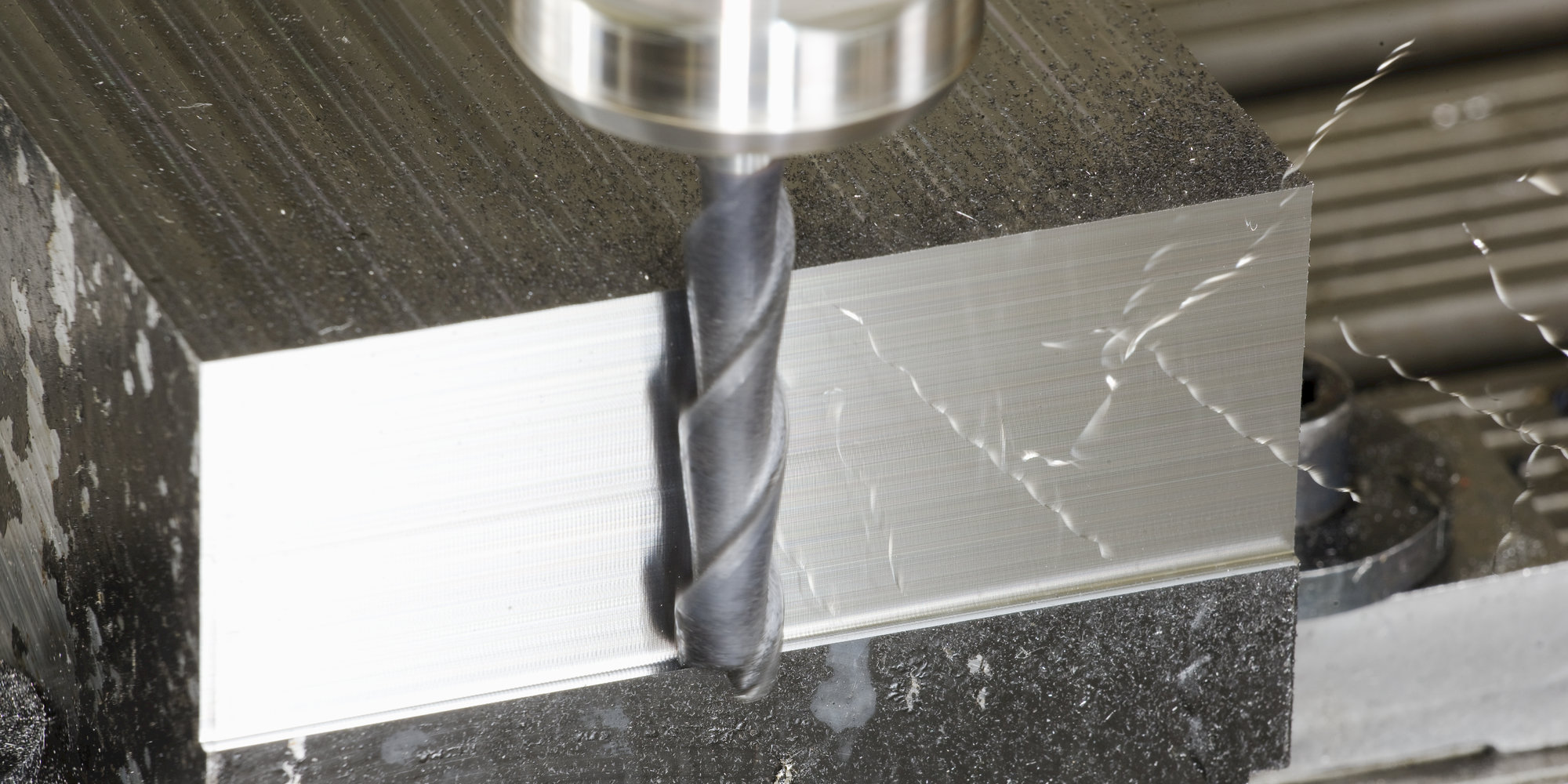
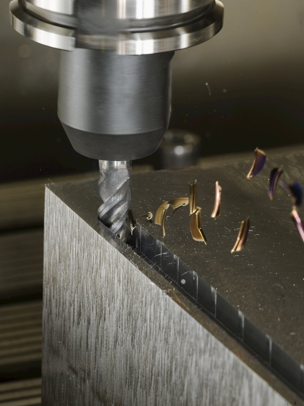
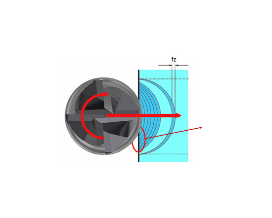
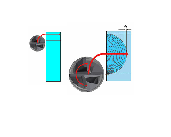
Loads on the cutting tool are mainly caused by the way the tool and its cutting edges enter the workpiece. In conventional or “up” milling, the cutter rotates against the direction of the feed, entering the workpiece at minimum chip thickness and exiting at maximum chip thickness. In climb or “down” milling, the cutter moves in the same direction as the feed, entering the workpiece at maximum chip thickness and exiting as the chip thickness decreases to zero. In both cases, the operation produces a tapered chip.
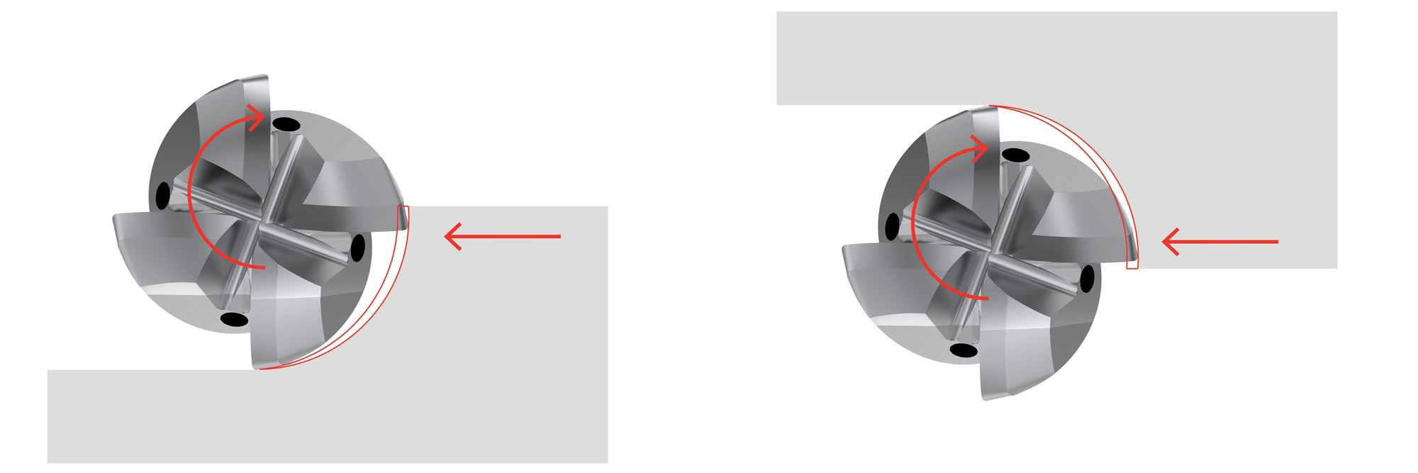
In most situations, tooling suppliers recommend down milling because it minimizes the rubbing and friction that occurs at the entry of conventional milling. It also facilitates heat transfer into the chip, protecting both the workpiece and the tool and, as the chips flow behind the cutter, it minimizes the risk of re-cutting them.
In general, down milling is preferable but in rare cases conventional milling might be an alternative, particularly on older, less stable machines with backlash issues.
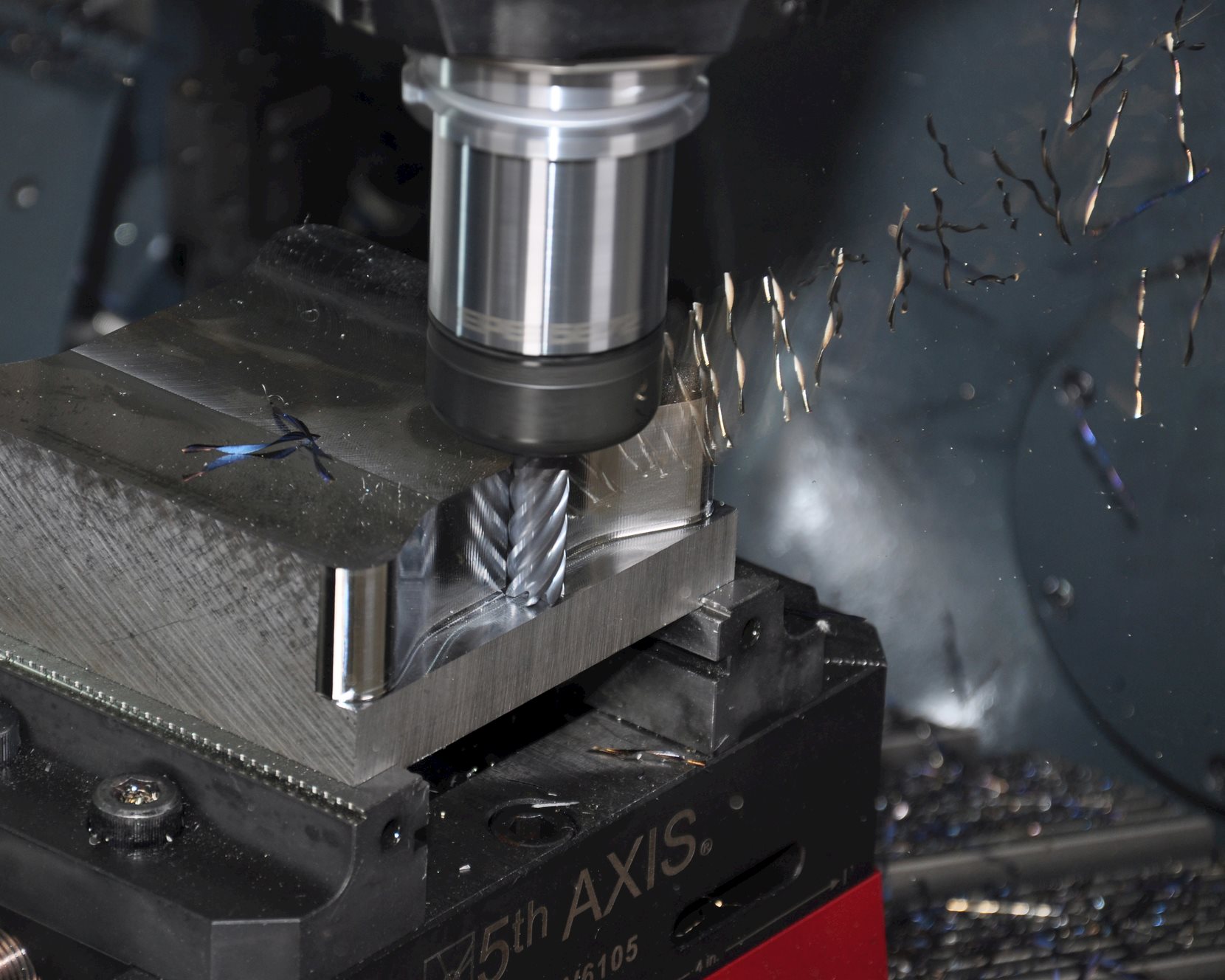
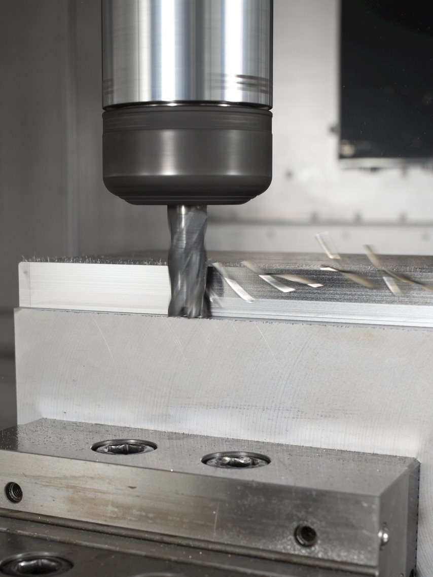
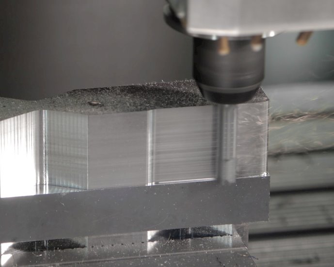
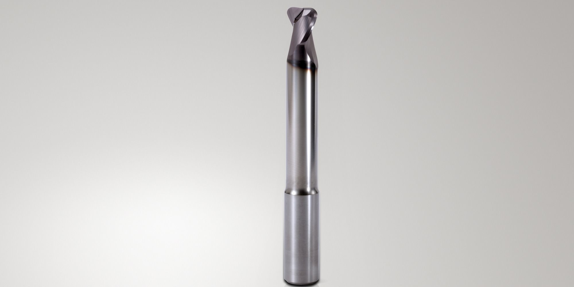
Always mount your solid end mill with the shortest possible overhang (the unsupported length outside the toolholder).
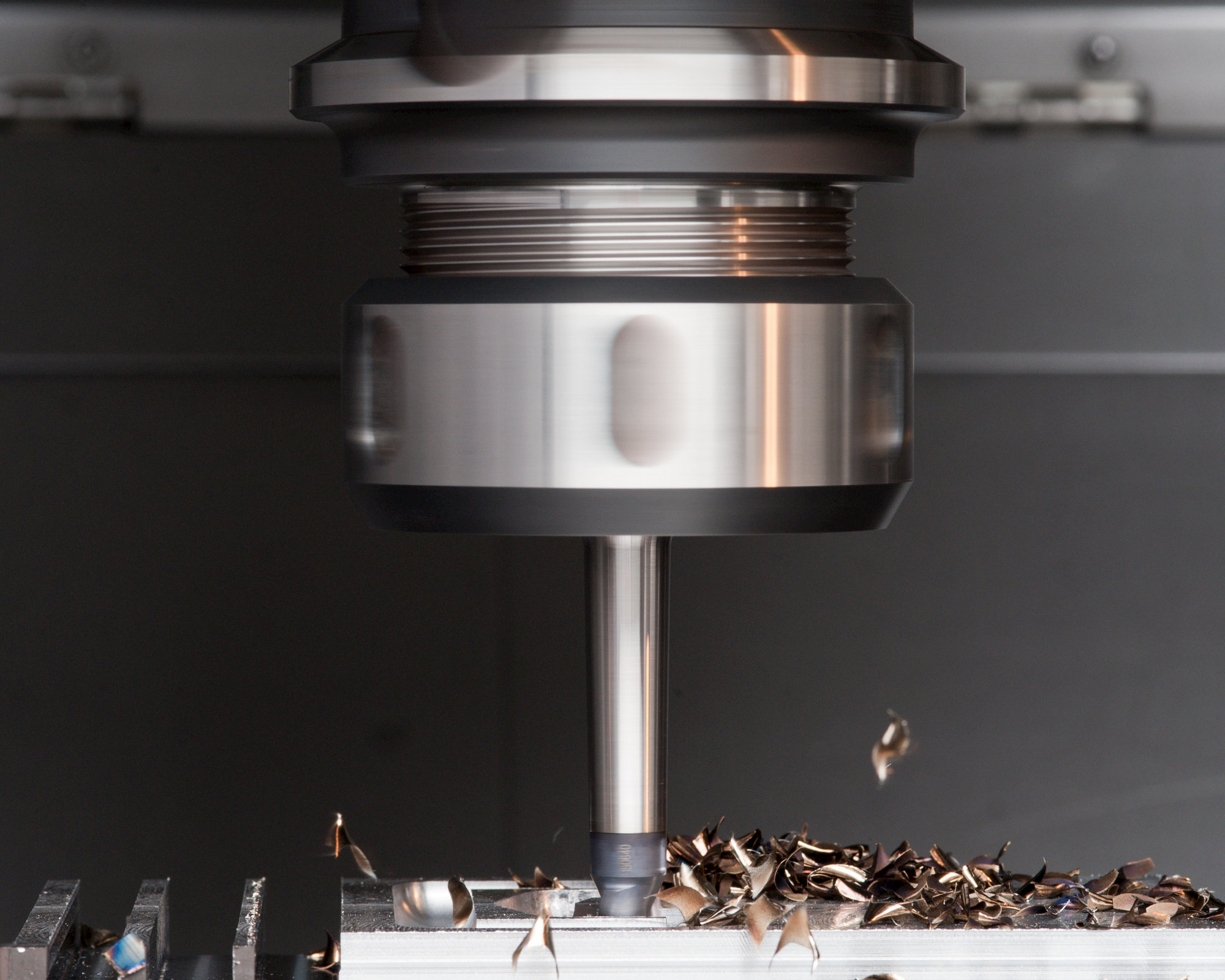
Milling cutters with a long tool length are more likely to vibrate and this will lead to cutting edge chipping.
These types of tools will deflect more during the operation which will also lead to faster flank wear.
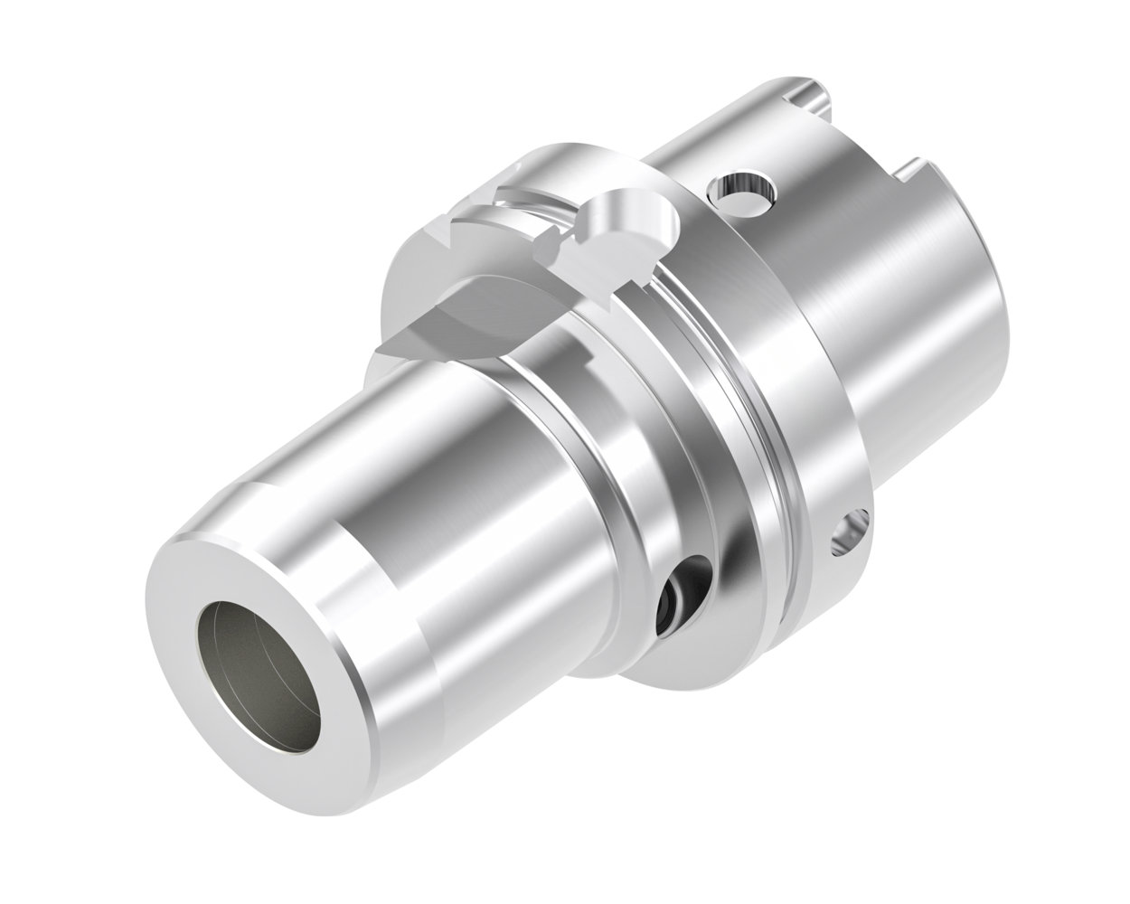
When assembling tools, it’s essential to follow some fundamental guidelines.
While it may seem straightforward, tools must always be mounted in the correct tool holder – the shorter and bulkier the better for optimal rigidity – and the fixturing must be completely stable to properly support the workpiece.
Ignoring these basics can lead to unsafe and hazardous working conditions.
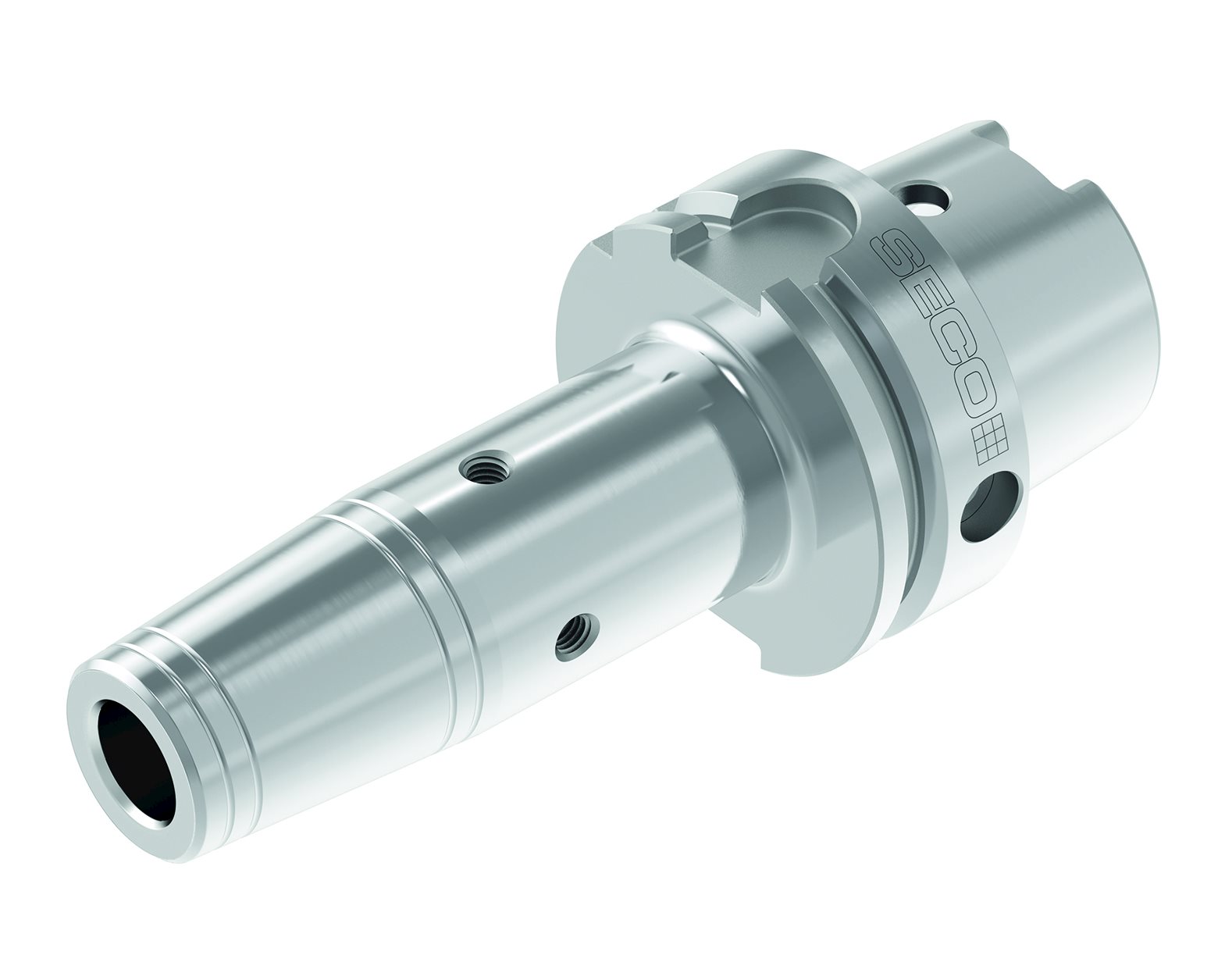
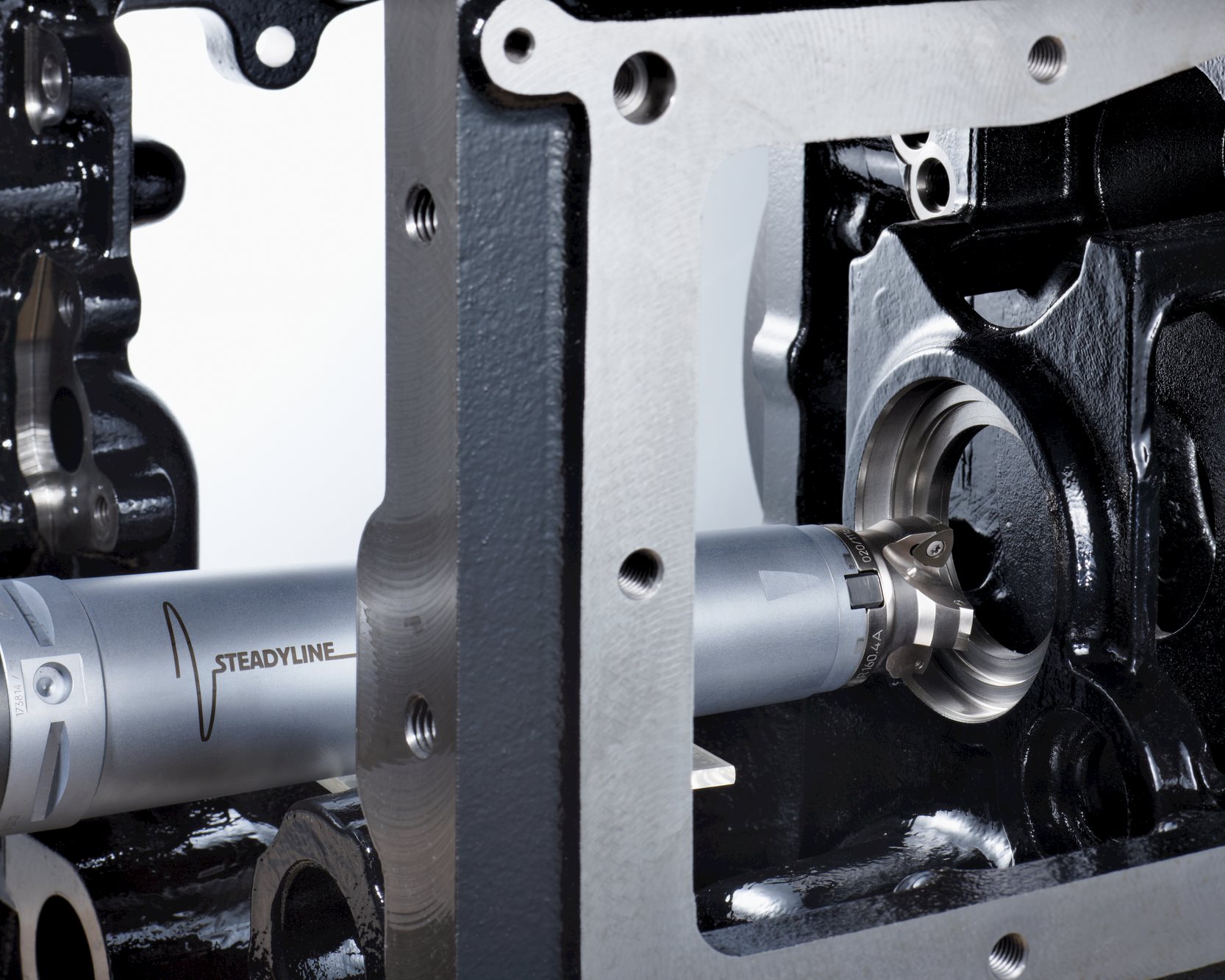
Selecting the appropriate tool holder is crucial for achieving optimal tool performance.
At high spindle speeds (above 12,000 rpm), using fine balanced holders is essential to ensure minimal run-out and to prevent micro-vibrations.
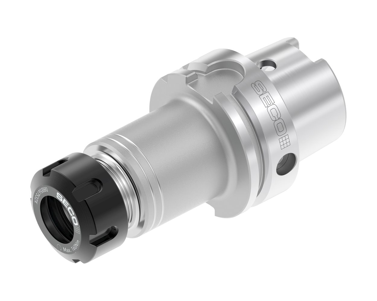 Additionally, advanced technologies like high-precision collet chucks or hydraulic chucks offer a damping effect that helps reduce vibration, which extends tool life and improves surface finish.
Cleanliness also plays a vital role. Dirt or chips on the tool or inside the holder can damage the bore and the tool shank, leading to reduced performance, dimensional inaccuracies, and increased vibration during machining.
Always clean the tool holder and the tool shank thoroughly before matching them together.
Ultimately, a high-quality, well-maintained tool holder is key to unlocking the best possible performance from your tooling setup.
Run-out is the degree to which a tool or spindle moves away from its intended rotational axis. The lower the total run-out, the better the distribution of cutting forces on each tooth and the longer the tool will last.
Run-out causes premature tool wear and excessive vibrations, which in turn can cause poor surface finish and even damage spindle bearings. Did you know, your tool life reduces by about 10% for every 0.02 mm of run-out?
Rolling into the cut is the practice of gradually increasing the feed rate and cutting depth as the tool meets the workpiece and is recommended for several reasons – it enhances the machining process and improves the overall quality of the finished part.
The specific application and material being machined may mean a few adjustments in the rolling strategy, but the general principle of gradual engagement is often more relevant than not.
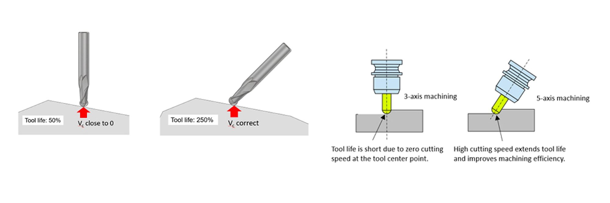
Spindle inclination in multi-axis operations allows a tool to approach the workpiece at the best angle, reducing end mill chatter and wear.
By tilting the spindle, a ball nosed tool can also maintain a consistent cutting speed, resulting in better surface finish.
This is especially important when machining complex surfaces or contoured parts.
The Machining Stability Lobes System is a key concept in machining dynamics that helps predict and manage vibrations during cutting operations. It’s essentially a system that allows machinists and engineers to analyze the stability of their cutting process so they can fine-tune parameters and avoid issues like chatter.
It’s based on the idea that certain combinations of cutting parameters like spindle speed, feed rate, and depth of cut, can either lead to stable or unstable cutting conditions. When these combinations are plotted on a graph, they form distinct “lobes.”
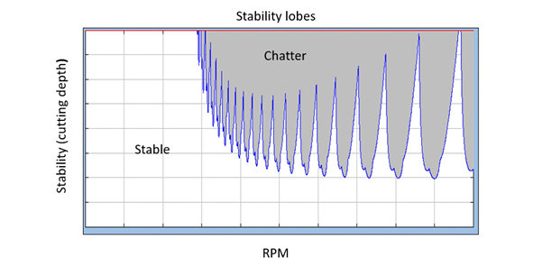
On this chart, the horizontal axis typically shows spindle speed (in RPM), while the vertical axis represents depth of cut. These lobes appear due to the interaction between the natural frequencies of the cutting tool and workpiece, along with the dynamics of the machine itself.
By referring to a stability lobes chart, machinists can pinpoint safe operating zones for a specific tool-material setup. This helps ensure smoother machining, free from chatter, and leads to better surface finishes and improved efficiency.
In short, the Machining Stability Lobes System is a powerful resource for optimizing cutting conditions and enhancing the overall quality of metal cutting operations.
This strategy is recommended to reduce vibrations in challenging areas like corners where conventional toolpaths can lead to unstable cutting conditions. Trochoidal paths allow the tool to roll into the cut gradually which reduces the sudden force peaks that cause vibration and chatter. It also allows for better chip flow, preventing tool overload and failure.
Sharing similar principles to trochoidal milling, adaptive paths maintain a constant chip load which minimizes force fluctuations and avoids vibration buildup. Variable helix angles are often used in this strategy to disrupt harmonic build up and reduce chatter.
High feed milling controls vibrations by pushing most of the cutting forces axially into the spindle rather than radially, which makes it more stable. High feed rates with small depths of cut lower the cutting forces and vibration, especially with long-reach tools. Consistent tool paths and rigid tool setups further dampen vibrations making this combination great for smoother, more stable machining.
This strategy keeps things smooth by using fast spindle speeds and lighter cuts, which means the tool doesn’t enter the cut too aggressively and maintains a stable cutting condition. The high speeds also mean the chips get out of the way quickly, keeping the cut clean and reducing heat. Plus, the machines and tools used for HSM are usually built to be extra rigid and precise, so dynamic loads are absorbed, and accuracy is maintained.
Vibration is an unavoidable part of solid end milling, but with the right strategies, tools, and set-up, it can be effectively managed or even prevented. From understanding the causes of chatter to applying advanced machining strategies like trochoidal and high-speed milling, every step you take toward stability will improve tool life, surface quality, and overall productivity. By staying informed and proactive, you can turn chatter from a challenge into a controllable factor in your machining success.